
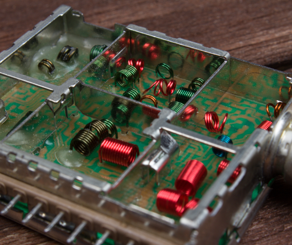
Air-core coil inductance calculator
Calculate the inductance of different coil and conductor geometries using the equations ECK used in the original tool.
ECK created these calculators to speed up recurring calculations in electronic design, RF circuits, antennas and inductors. Choose the matching geometry, enter the dimensions in centimeters and get the estimated inductance.
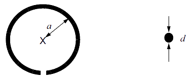
Single-turn circular loop
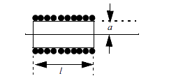
Single-layer circular coil
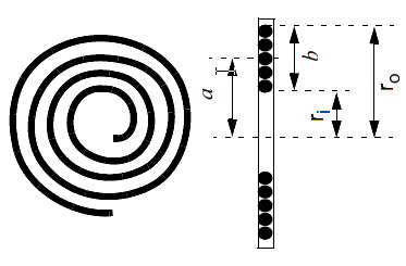
Flat spiral coil
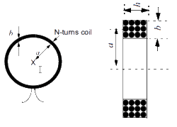
Multilayer circular coil
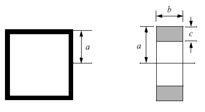
Square coil
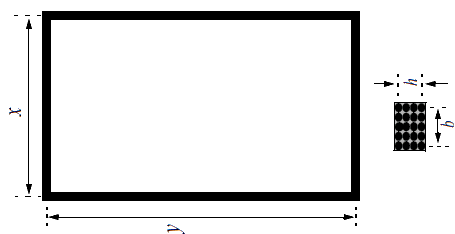
Rectangular multi-turn coil
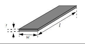
Straight conductor inductance
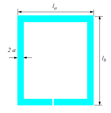
Single-turn loop used as an antenna
About the formulas
The equations were carried over from ECK’s original tool. For the single-turn antenna geometry, the reference noted in the original code is Microchip Application Note AN710, Antenna Circuit Design for RFID Applications.
How to use the air-core coil calculator
The coil calculator covers several geometries because inductance depends on more than the number of turns. Diameter, winding length, turn spacing, conductor dimensions and coil shape all change the result. So before calculating, select the geometry that best represents the component you will build.
The results are useful in the early design stages of RF circuits, filters, resonant networks, antennas, coupling circuits and other circuits that use inductors without a magnetic core. The tool lets you quickly estimate the order of magnitude of the inductance and compare construction options before building a prototype.
As with any calculation based on mathematical models, the value obtained is an estimate. Mechanical tolerances, nearby metal, operating frequency, parasitic capacitance and the real characteristics of the conductor can make the measured inductance differ from the calculated value. In critical applications, the component should be built and measured under real operating conditions.
In product development, the calculator also helps assess how geometric changes affect the component. You can change the number of turns or the coil dimensions and immediately see the predicted effect on inductance. This reduces trial and error at the bench, although it does not replace experimental validation.
The tool is part of the technical content ECK makes available to support electronic engineering work. For real applications involving hardware, firmware, instrumentation and embedded systems, see our electronic engineering projects.
Need to develop or validate a circuit?
ECK works on hardware development, embedded systems, RF and instrumentation.